Radial Swirler Multi-Spray Injection CFD
Radial Swirler Multi-Spray Injection CFD

Overview:
The modelling of a 6 slot radial swirler combustor at arbitary conditions similar to a power generation gas turbine. The model uses 3 fuel sprays and show the fuel air mixing and chemical reaction.
The model
The model is representative of an industrial gas turbine but is not specific to any particular machine or operating condition. It is intended to demonstarate the capability of sprayFoam for multi-injection and reaction modelling.
The model uses a radial swirler having 6 swirl slots and 3 individual fuel sprays that are positioned on the burner back face at a diameter outside that of any aerodynamic vortex core. This would ensure that the fuel sprays are not exposed to the very hot combustion gases during operation which would lead to the internal spay nozzle pasages blocking due to coke formation in the tiny nozzle fuel passages.
Although sprayFoam allows for the configuration of 3 conpletely different sparys this model has used 3 identical fuel spray distributios and injection parameters. Therefore, should a development of in-field issue arrise for this burner, a CFD model could be created that examines partially blocked nozzles.
The model flows the 3 fuel sprays for several iterations before the fuel air mixture is ignited using a patch inside the model of a high temperature spehere - simulating a spark kernel. The ignition process produces a pressure field due to the rapid change in density. This is seen in the transient alteration of the fuel spray trajectory. The gif image below shows the fuel sprays up to the point of ignition.
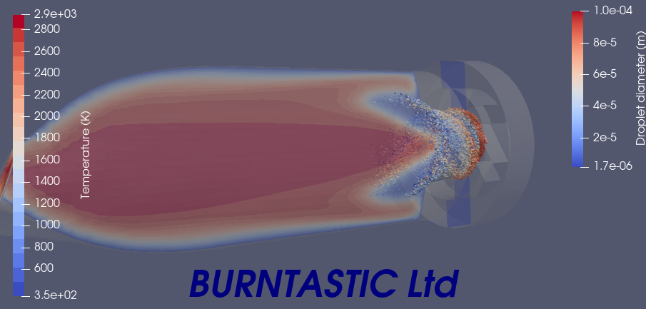
Once ignition has occured the strong reverse flow within the swirling vortex core provides very high flame stability once the flame is ’trapped’ within it. The flame cannot expand towards the fuel sprays due to the high speed air flow.
The above is seen in this still showing the flame and sprays
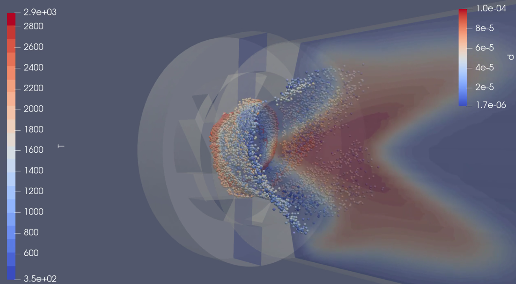
The model shows the flame stabilizes in the vortex core of the burner. However, the CFD model does not simulated the effect of flame strain and therefore cannot fully model premixed flame stability. In this case the liquid fuel spray is diffusion witrh partial premixing.
Animations
The model is available to see in a 1 minute animation on youtube.
Conclusion
The objective of the model was to demonstrate the application of sprayFoam in a working combustor.
Further modification to the model can be done to explore different reaction schemes - e.g. kerosene with much more reaction steps which would allow for the prediction of NOx and CO formation and how this can be minimised in this design configuraton.
The sprayFoam solver can also provide a means of analysing in-field service issues where for example a poor atomiser has been installed to understand failure modes. This approach can also provide guidance on the robustness of the design in the development phase where some idea of the variation in the fuel spray quality and its impact can be determined.
Latest Posts

Me262 Combustor CFD
11 Apr 2025
Radial Swirler Multi-Spray Injection CFD
11 Feb 2025