Me262 Combustor CFD
Me262 Combustor CFD

Overview:
The modelling of a Me262 combustor using openFoam. This enables the reported aircraft engine handling characteristics to be understood as the result of very weak flame stability. This weak stability results from the flame stabilizing on the fuel spray wake. The CFD modelling shown here used sprayFoam solver and a reduced C7H16 reaction scheme.
Introduction
The Me262 Juno-004 engine combustor is a rather unusual design in that the fuel injector directs the fuel spray upstream and has a ‘cage’ type air mixer. This forward facing fuel spray creates a significant aerodynamic wake behind the injector where the flame may stabilize. The size of the wake is a function of the fuel spray size which is in turn a function of the total fuel flow. This means that the flame stability is directly linked to the fuel flow rate. Any rapid changes to the fuel flow rate will change the size the the flame stablizing wake.
First hand testimony
Captain Eric Brown – a British test pilot who flew the Me262 remarked that the engines were incredibly sensitive to throttle movement. He stated that the German pilots would set the throttles to take-off and once airborne would throttle back to 70% power never touch the throttles again until back on the ground. This then shows the key design weakness of the combustor – flame stability.
This modelling was partially driven by the desire to understand this weakness.
The Model
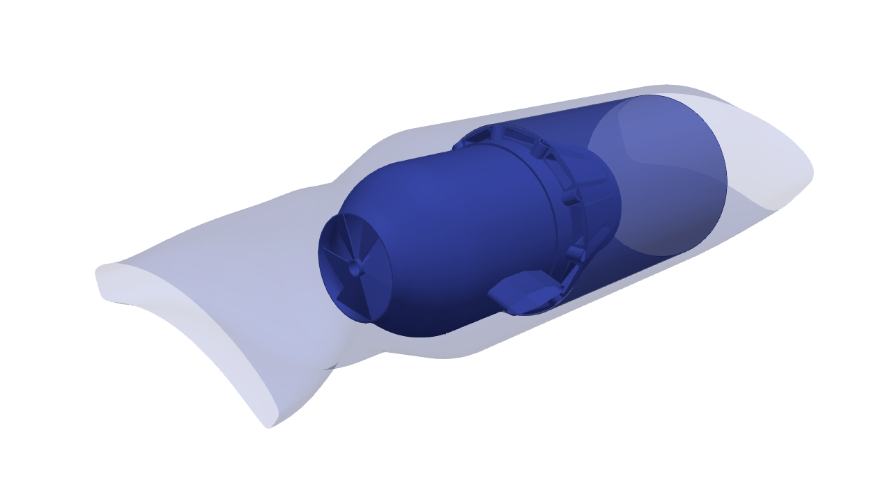
The CFD model linked here and the still images contained in this blog post show the fuel spray and the flame stabilization behind it. The unusual ‘mixer’ section helps to even out the temperature profile of the hot gases entering the turbine. This is incredibility important due to the use of wrought steel in the engine components – due to shortages of high temperature alloys. The combustor too is fabricated from wrought steel.
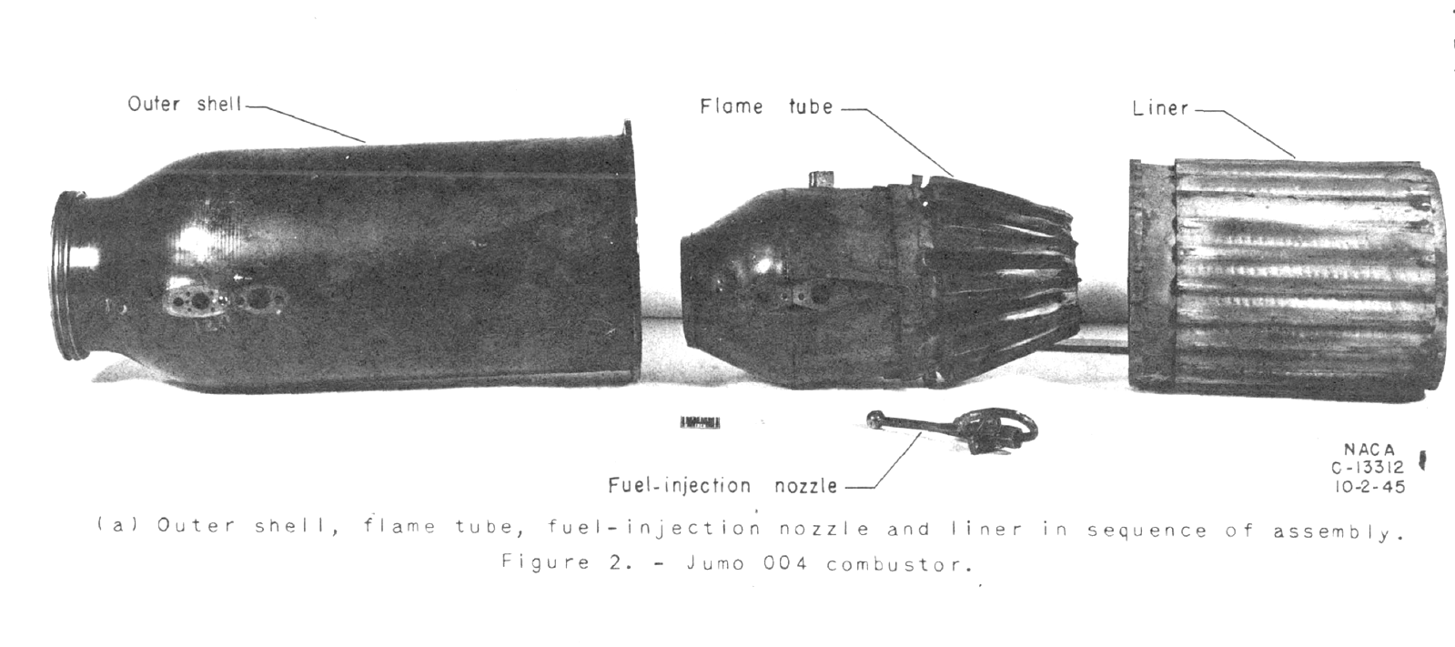
The model was constructed from drawings in a US research report done on captured engine combustor components. NACA RM E7F03 Performance investigation of a Jumo 004 Combustor By Robert Miller 1947. This helped greatly, not only in the CFD model construction but also in confirming the operation of the fuel injector.
Initially, the fuel spray was assumed to be directed downstream. It is possible that the original German designers intended for that to be the case as well. However, Flame stability in this case would have been very bad – to the point of unusable since the swirl generated by the air swirler is actually high high enough to form a stable recirculation bubble.
The NACA report contains a lot of information and reflects the effort made by the Allies to reverse engineer captured German technology.
The report is available online at: https://ntrs.nasa.gov/citations/19930085630
Several key images are contained int he report. The first shows the combustor ‘system’. The liner, the burner or flame tube and injecter.
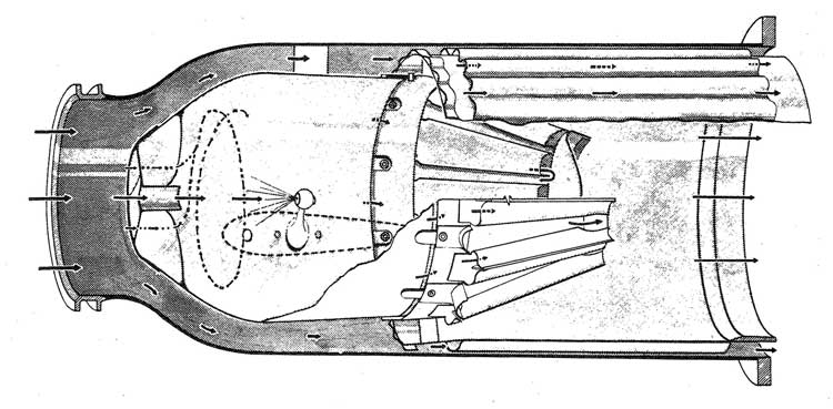
The second image is particualarly important for this study in that it graphically shows the position and direction of the fuel spray in a sectional view of the complete combustor assembly.
The third image shows the flame tube with the fuel injecter and igniter or spark plug. Shown too are the two strut supports that hold both the injniter and fuel injector but also a small open pipe to connect each combustor with its adjacent neighbour. The function of the latter is to equilize pressure between all combustors and balance the flows.
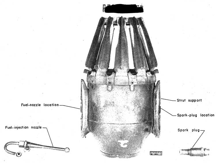
The support struts were simplified for the CFD modelling. This simplification does not impact on the validity of the model or its predictions.
Evidence of development issues
One interesting feature of the forward flowing fuel spray is that a portion of the spray that evaporated close to the fuel injector is seen to be captured in the wake of the swirler central hub. This hub has a central hole cut in it to provide air flow which if it were not present, would result in an attached flame and a very high temperature in the hub. It is possible that the original German engineers encountered this and to avoid burn-through issues, simply cut a hole in the central hub that moved the flame and provided extra cooling to the hub.
As with Frank Whittle’s jet engine, the combustor must have been an area of considerable concern. In Whittles case, frantic efforst to ‘fix the combustor’ resulted in nearly 100 combustor prototypes. Details of the German development issues are not readily available but they enjoyed lavish funding where Whittle struggled to get the funding he did.
Modelling
The CFD model was created in FreeCAD with the geometry exported in STEP format to Salome software suit from which more high precision STL geometries can be exported ready for snappyhexmesh. The advantage of the use of Salome software is that each SLT CAD surface can be labelled allowing for higher level of control on the meshing.
The CAD geometry
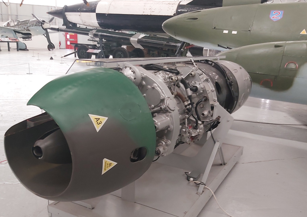
The CAD geometry was produced from the NACA report and some personal measurements taken from a museum exhibit at RAF Cosford. The curved inlet and outlet duct geometries were created using a Burntastic duct development tool. This allows for control over the surface development and provides a parametric tool to enable rapid geometry creation.
The cross-firing duct arrangement on the original engine is achieved using stamped metal parts. In the CAD model a simplified geometry is used. This does not alter the main flow or the CFD predictions. It does however ensure greater numerical stability and ease of meshing.
Spray distribution
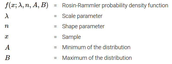
The sprayFoam model uses a Rosin-Rammler size distribution. This is described by the following:
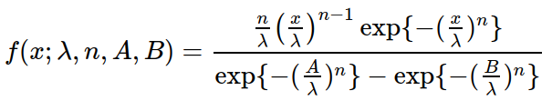
Where:
In this model the following values were taken:
Lambda = 8E-5
n = 4.0
Min = 5.0E-6
Max = 1.2E-4
The resulting size distribution can be seen in the picture below:
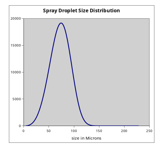
It should be recognised that this is a pure guess for this particular spray since no data exists. However, it is clear that there must have been some very large droplets generated to provide a reasonable sized aerodynamic wake. Too many small droplets would have vaporised quickly leading to virtually no flame stabilization. Hence a size distribution with a reasonable proportion of large droplets was used. Clearly, this configuration can be adjusted and a sensitivity analysis could be done but for the purpose of understanding the general operation and characteristics this appears to have been good enough.
Results
The results of the CFD model show the flame stabilization locations and how sensitive they are to fuel flows.
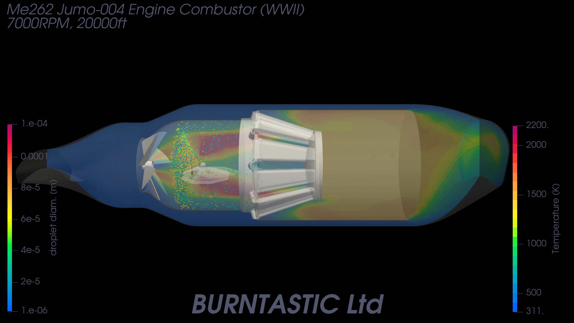
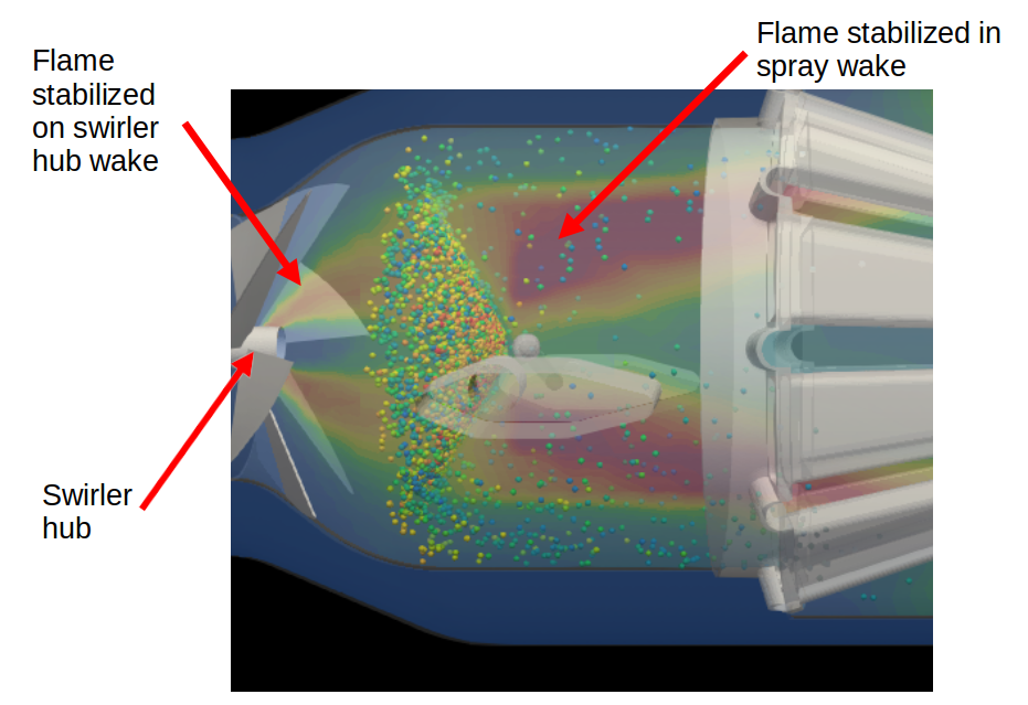
Zooming into the region behind the air swirler the flame position behind the fuel spray is clear as too the flame that is anchored on the air swirler hub. The central air flow though the hole in the hub is clearly lifting the flame.
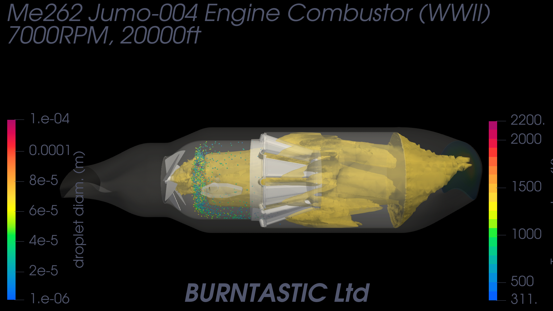
An iso-surface plot of the temperature regions shows the flame position and the effect of the mixer section or ‘cage’.
Animations
The model is available to see in a 3 minute animation on youtube.
Conclusion and Comments
The objective of the modelling was to demonstrate openFoam and the sprayFoam solver capabilities. It was also to understand the combustion system as used on the Jumo-004 engine. This has been done successfully.
Further investigation by changing the spray droplet size distribution or extending the chemical reaction mechanism would provide further information on the sensitivity of the spray and the emissions performance but those features would not significantly add to our understanding of the combustor its operation and development. This modelling has demonstrated the benefits for analysis of historical combustor designs in that it has shed light on the possible development issues and how the designers worked around them given the limited materials they had available.
One key feature of the combustor that is at first difficult to undertsnad is the ‘cage’ type air mixer. On display engines its function is not imediately obvious or where the flame is located. This analysis shows that the flame is located upstream of the ‘cage’ and imediately behind the fuel spray.
If you found this interesting or have questions arising from it, you can contact me via the contact page on this website.
Latest Posts
Me262 Combustor CFD
11 Apr 2025
Radial Swirler Multi-Spray Injection CFD
11 Feb 2025