OpenFoam - radial swirler burner
OpenFoam - radial swirler burner
Overview:
Complex parametric models can be created that are easily imported into OpenFOAM
Introduction
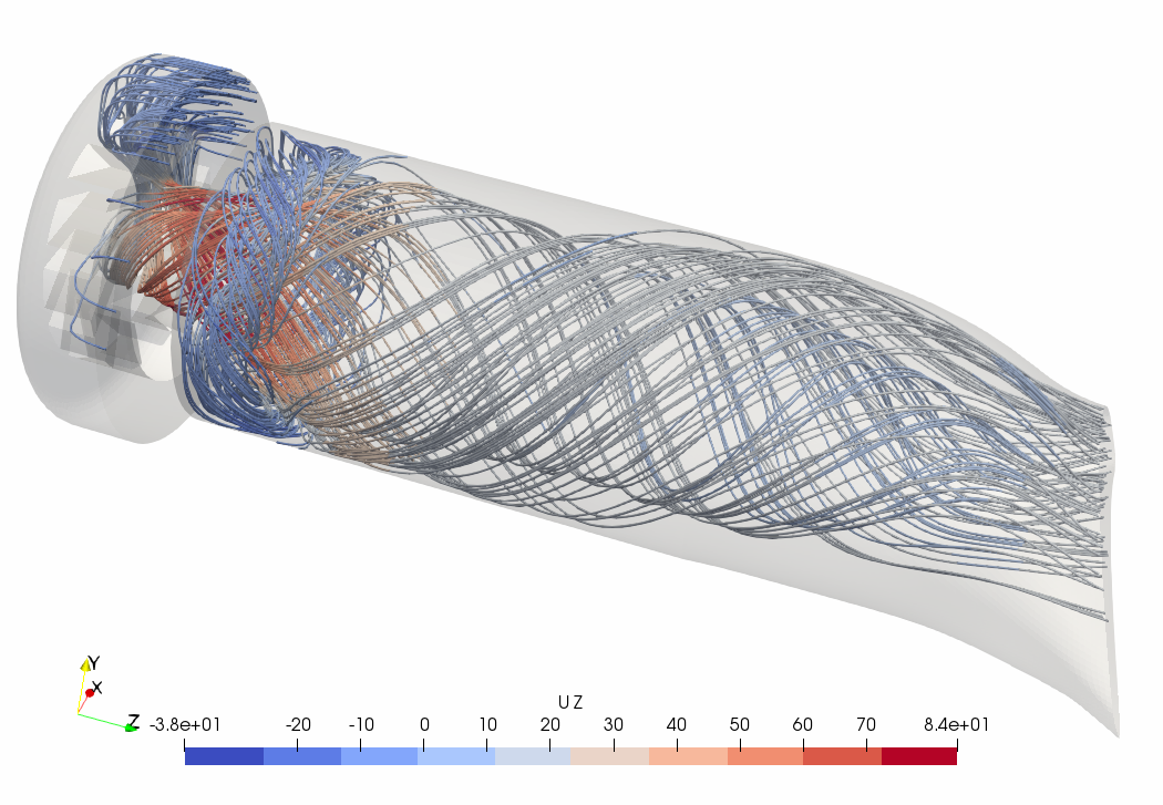
This is a generic radial swirler burner designed to work on industrial gas turbines for power generation. The geometry is not specific to any particular burner.
The model was created in Salome software. The model is defined in a python script in which all the key geometric parameters are defined. It is therefore possible to use this in a fully parametric analysis of the geometry, so that flow filed changes can be linked directly to geometry modifications.
The transition duct section of the geometry is defined using around 10 key parameters allowing for various types of duct to be studied for internal and external aerodynamic flows.
Where these models can be used
The model shown is an isothermal flow case and can provide initial concept design data for the selection of design candidates for either further detailed analysis or hardware build.
This particular geometry is generic and doesn’t include fuel injection ports.
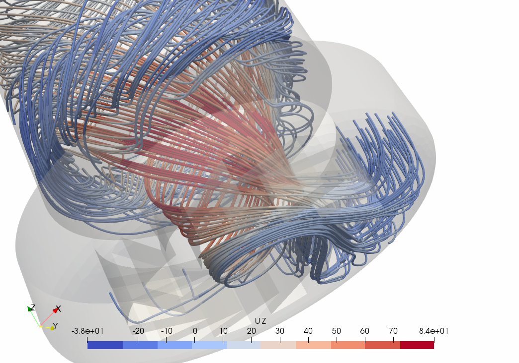
The streamlines show the flow through the swirl slots and out into the combustor. The central vortex is clearly visible.
The model uses an unstructured grid based on the salome implementation of Netgen. In this 3D model the Netgen boundary layer function is implemented on the slot, prechamber and combustor walls.
Python code implimentation
Briefly, the python script must contain the following header section.
 1import os
 2import math
 3
 4import sys
 5import salome
 6
 7salome.salome_init()
 8import salome_notebook
 9notebook = salome_notebook.NoteBook()
10sys.path.insert(0, r'/home/nigel')
11
12###
13### GEOM component
14###
15
16import GEOM
17from salome.geom import geomBuilder
18import math
19import SALOMEDS
20
21geompy = geomBuilder.New()
The parameters defining the transition duct are contained in the python script and are shown below
 1# duct parameters
 2
 3comb_diameter       = 250.0             # Combustor diameter (mm)
 4duct_number         = 8                 # Number of ducts
 5NGV_tip_radius      = 420               # NGV tip radius (mm)
 6NGV_root_radius     = 350               # NGV root radius (mm)
 7comb_cant_angle     = 35                # Combustor cant angle (deg)
 8duct_axial_length   = 280               # Duct axial length (mm)
 9Influence_a         = 0.22              # Influence factor Fa - cord centre line
10Influence_b         = 0.52              # Influence factor Fb - cord centre line
11NGVin_Angle         = 0                 # NGV Inlet angle NGVin_Angle
12comb_in_Angle       = 0                 # Combustor Inlet angle comb_in_Angle (keep at 0 most times!!)
13cord_inter          = 10                # Intervals/descretisation on cord line
14Na                  = 5.2               # Bottom Control Na
15Nb                  = 3.1               # Top Control Nb (more nozzle like as -> 0)
16corner_control      = 5                 # Corner Control Nc
17corner_max          = 5                 # Maximum Corner Cmax change this to make the exit square or not
18corner_min          = 2                 # Minimum Corner Cmin
19ellipse_discret     = 20                # ellipse discretisation
When the model and meshing is completed, boundary faces need to be defined to enable better import into openFOAM. A script file is used to enable adjustment of these boundary patches prior to the OpenFOAM run.
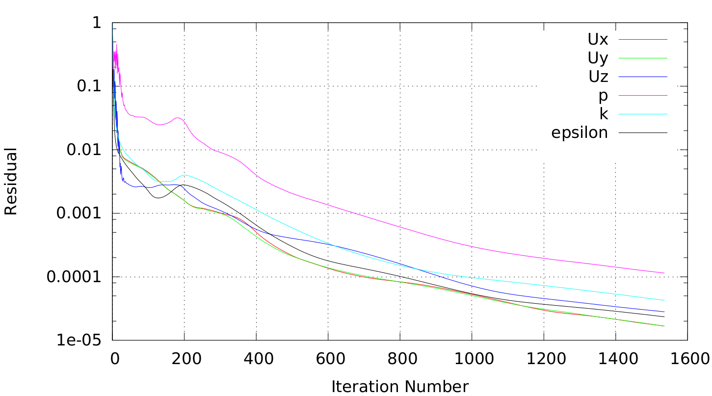
Calculations for highly swirling flows generally require a Reynolds stress turbulence model to correctly capture the flow field. Prior to activating the Reynolds stress model the simpler k-epsilon model is used and the convergence history for that is shown below.
Conclusion
The modelling of a representative gas turbine combustion system using open source tools has been demonstrated. The use of an unstructured mesh is used here but a structured mesh is possible using openFOAM’s snappy hex mesher based on the CAD export from salome.
While the use of such simplified mesh and modelling has its limitations, the use of open source code and the ability for parametric studies opens the door for optimization analysis at affordable economic levels. This then allows small companies top offer this analysis service while at the same time making possible scaling of the optimization to include as many design and operational parameters as the client may need.
Latest Posts
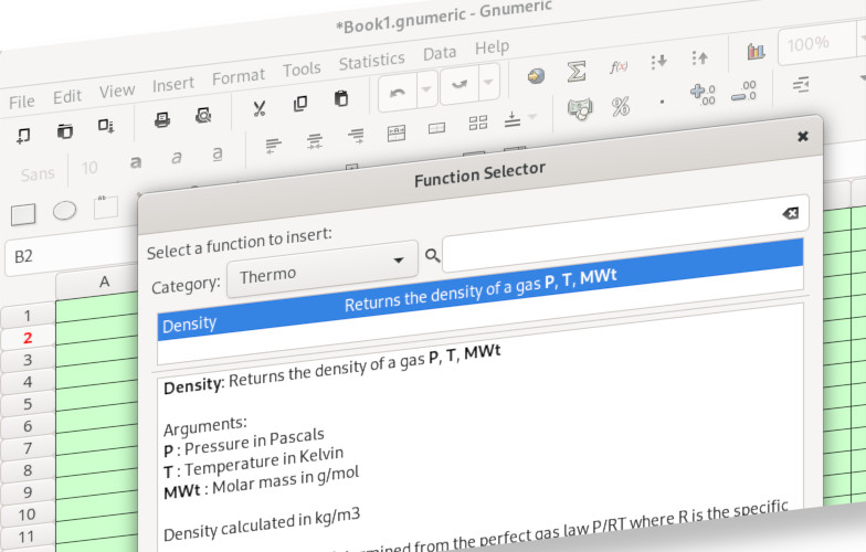
Gnumeric - function writing tutorial
11 Apr 2023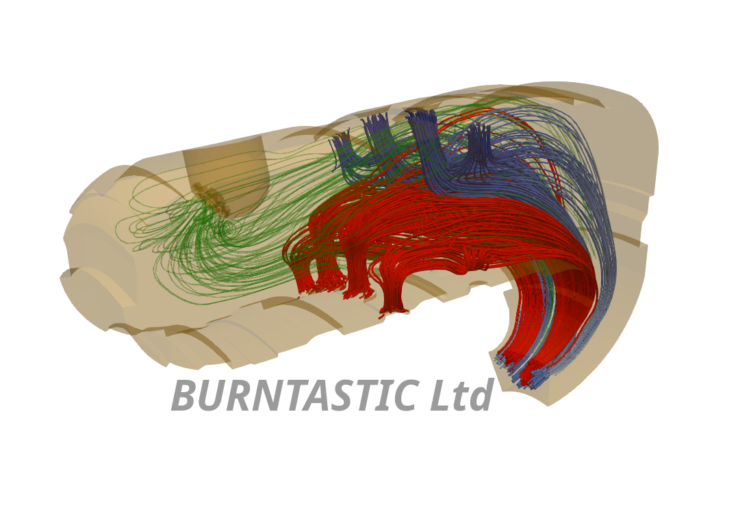
OpenFoam - Micro Combustor
09 Apr 2023