OpenFoam - Micro Combustor
OpenFoam - Micro Combustor
Overview:
Micro GT Combustor analysis using openFOAM. Methane, kerosene and hydrogen fuels
The Interest in Micro Turbines
Micro turbines have attracted much attention recently due to their small size and relatively high power output. For applications where combined heat and power (CHP) are needed they provide an excellent package. They do require specialist maintenance which has generally favoured gas engines over them. Applications for emergency power in remote locations are clear, but also in small enterprises that need semi off-grid solutions. Recently, the drive towards hydrogen fuels has seen diesel engine conversion done with considerable success by companies like JCB. However micro turbines offer an advantage in static CHP in that they can in theory work with a wide range of fuels and allow for on-line fuel switching. This later option has been applied to industrial sized gas turbines for many years. Due to the continuos combustion process in a gas turbine, the specialist lubrication oil issues on gas/diesel engines doesn’t arise when using hydrogen - although this is not the issue it once was.
On-line fuel switching from diesel to natural gas has been available in industrial gas turbines for some time. The basic principle is that the machine requires a constant combustor exit temperature during the fuel switch, as long as the combination of both fuel’s energy flow into the combustor maintains a constant total energy the combustor exit temperature can be held constant. As one fuel’s flow is ramped down the other is ramped up and the gradients of the respective ramps are a function of the fuel’s heating value. This provides a huge advantage to machine operators as they do not need to have a guaranteed fuel supply and can switch over as and when needed. Typically the on-line fuel switching can be done within a minute, thus providing a relatively speedy response.
Operation of a combustor using different fuels does pose a variety of design problems. For fuels with high hydrogen, the combination of high flame speed and flame strain resistance leads to flames that can attach to the fuel injection device. Conversely, fuels with a relatively low energy content tend to ’lift off’ and become unstable. This change in fuel chemistry is a major challenge in combustor design.
An example micro combustor
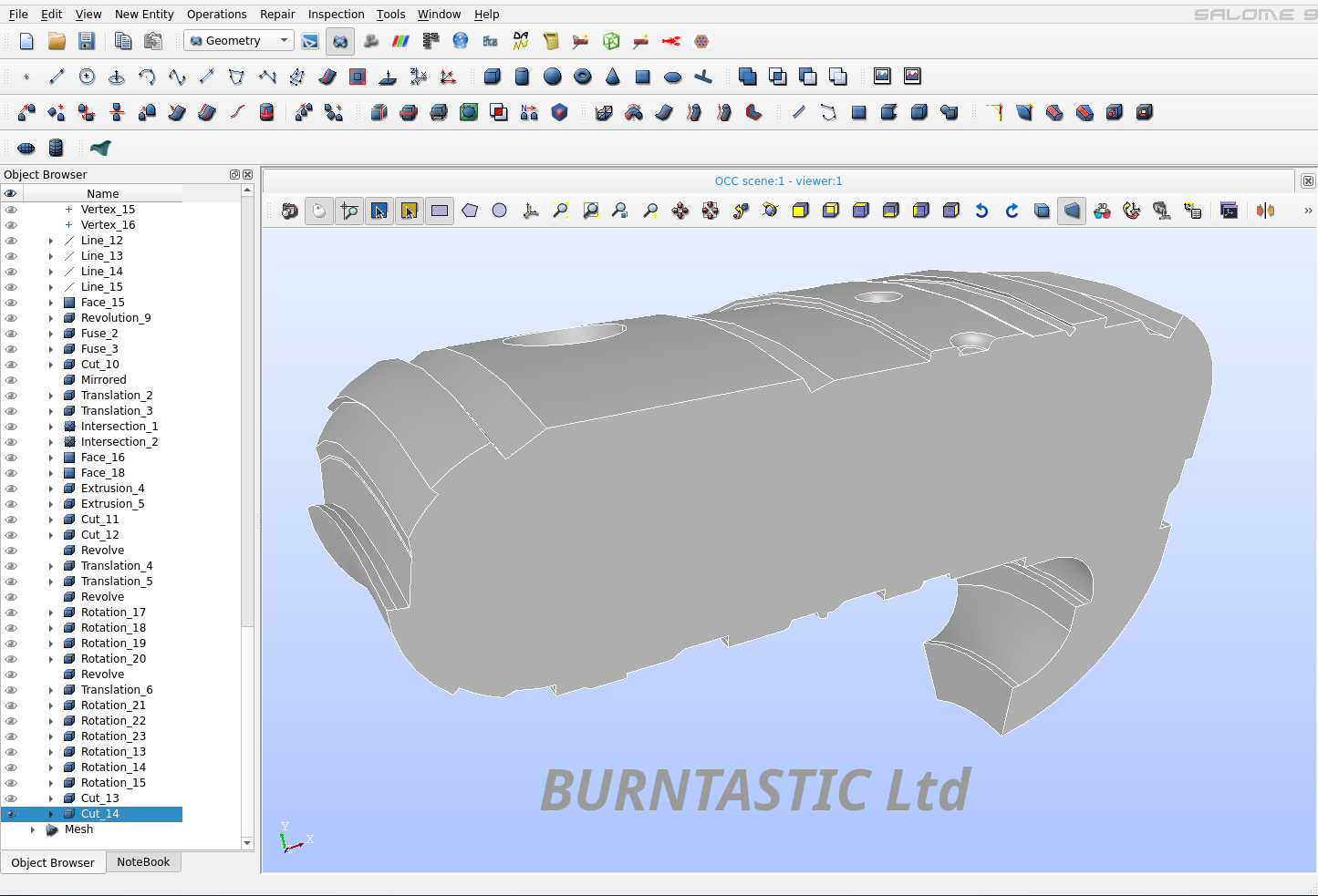
A reverse flow micro combustor is shown below. The combustor length is approximately 5.75 inches and an overall diameter of approximately 8.75 inches. As can be seen the combustor is a reverse flow and is configured for use in a compact power unit. The unit is intended to use radial compressors so the machine pressure ratio is not too high.
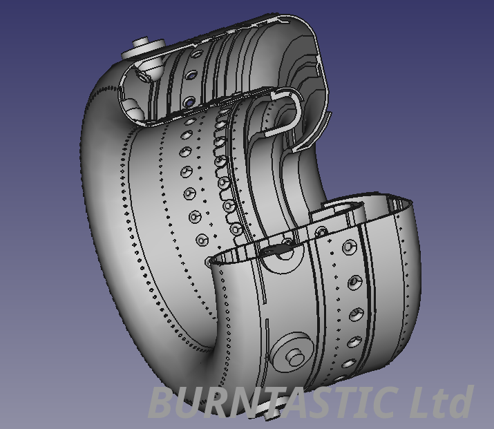
The fuel injector is housed inside a domed assembly that fires the fuel forward or against the main gas flow. A single row of dilution holes is configured on the outboard liner wall with one row on the inboard liner. In front of the inboard dilution holes is a single row of primary jets.
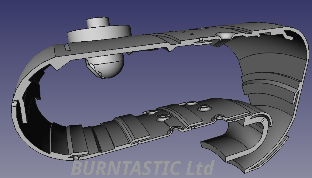
As can be seen from the above FreeCAD model picture that geometry is modelled as is without reference to the internal ‘fluid’ volume that the CFD calculations need.
Modelling
FreeCAD
FreeCAD was used to produce the full 3D model using its parametric workflow approach. This produced a very detailed geometry that can be used for structural analysis. The internal volume for the CFD calculation proved to be difficult to extract without considerable effort. This is partly due to the large number of cooling holes, primary and dilution jets that need to be ‘blanked’ as the casing flow was not modelled.
However, elements from the FreeCAD part list were exported in STEP format and subsequently imported into Salome. This proved to be highly effective because while Salome has a somewhat tedious interface compared to FreeCAD, it does allow for flexibility. The strengths of both software packages can be used to produce a workable CFD model quickly. Furthermore, the python scripting in both packages allows for a high degree of automation especially since both applications can be run in batch mode.
Salome
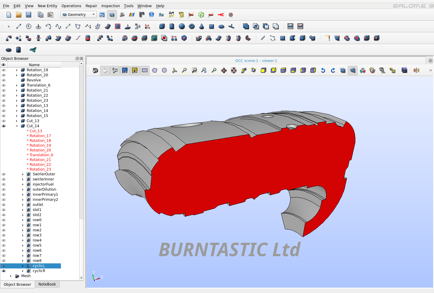
The fluid volume was created using Salome software. This was a combination of imported STEP files from FreeCAD and Salome’s own geometry creation engine. Although this was not ideal, the process is auto scripted in python allowing for a high degree of subsequent automation for parametric model study.
Within Salome the geometry model faces can be named. This is crucial for openFOAM import. The most important face definitions being the input faces and the outflow faces. However, for sector models like this, the cyclic symmetry faces need to be specified as shown below.
OpenFOAM
The mesh created needs to be exported as a UNI file. This can be handled by the openFOAM mesh import utility. In this particular case the boundary file produced need to be edited so that the patch names for the walls are changed to be of type “wall”. However, the most important change is for the cyclic boundaries. These need to be specified as:
cyclicL
{
    type            cyclicAMI;
    neighbourPatch  cyclicR;
    transform       rotational;
    rotationAxis    ( 1 0 0 );
    rotationCentre  ( 0 0 0 );
    matchTolerance  1;
    nFaces          3633;
    startFace       811310;
}
cyclicR
{
    type            cyclicAMI;
    neighbourPatch  cyclicL;
    transform       rotational;
    rotationAxis    ( 1 0 0 );
    rotationCentre  ( 0 0 0 );
    matchTolerance  1;
    nFaces          3633;
    startFace       814943;
}
The values for the nFaces and startFace are specific to the mesh. Normally, openFoam creates the Boundary file with the cyclic symmetry faces defined as “type patch”. This is because it defaults to these values. The used should edit these entries with the type as indicated above. Note that the rotation axis needs to be specified for the specific model. If the symmetry axis is incorrect the model will produce some strange results…
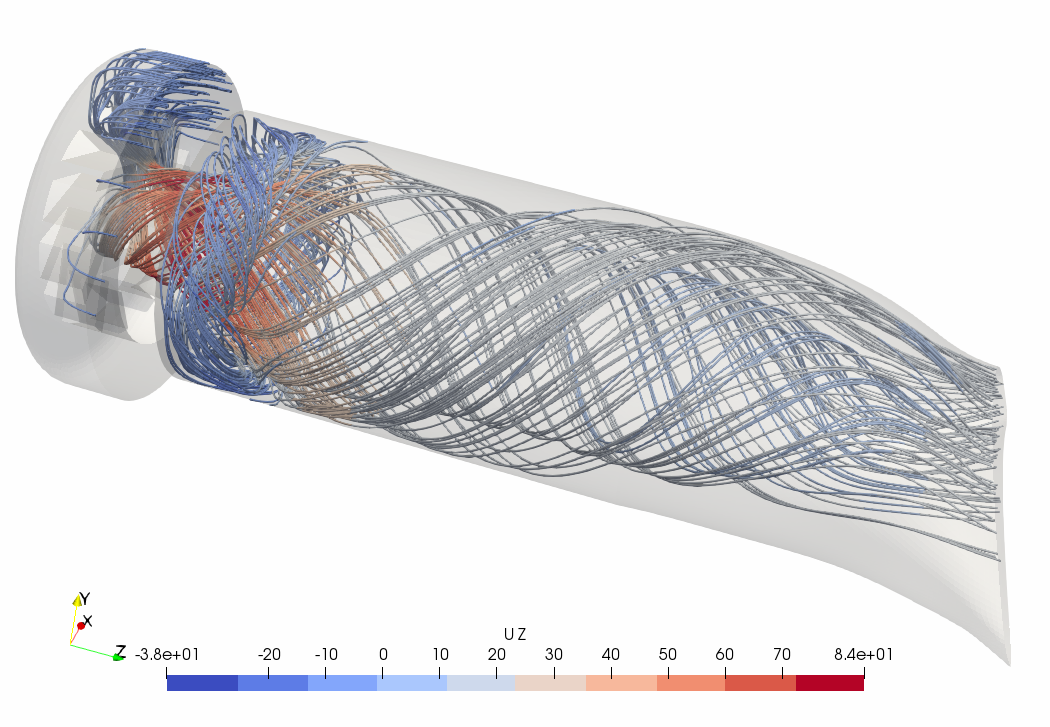
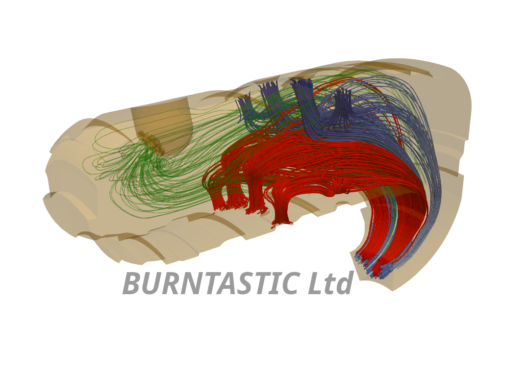
ReactingFOAM solver was used. This allows for the chemical reaction to be turned on or off as needed. It also allows for the fuel placement to be modelled in the case of the non-reacting flow - which is useful in assessing the degree of mixing uniformity.
Using the chemical properties dictionary, it is possible to switch fuels. In this study, methane, JetA and Hydrogen fuels were modelled. The JetA fuel modelling used a simplified 2-step reaction scheme.
results

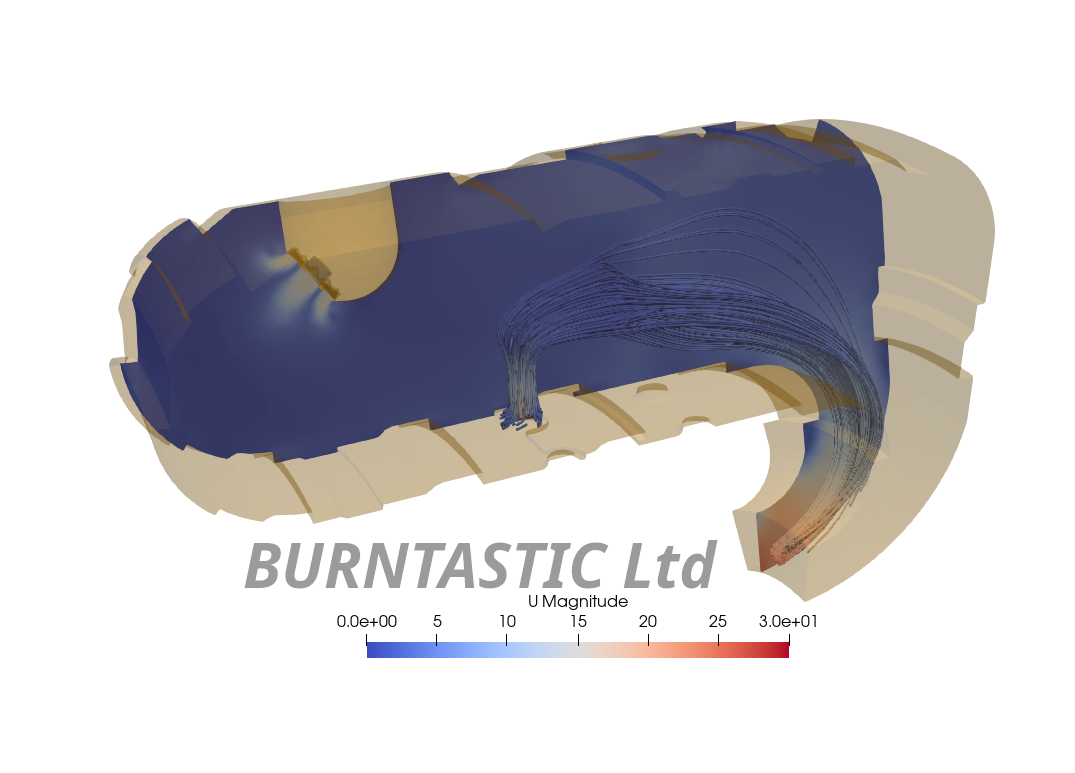
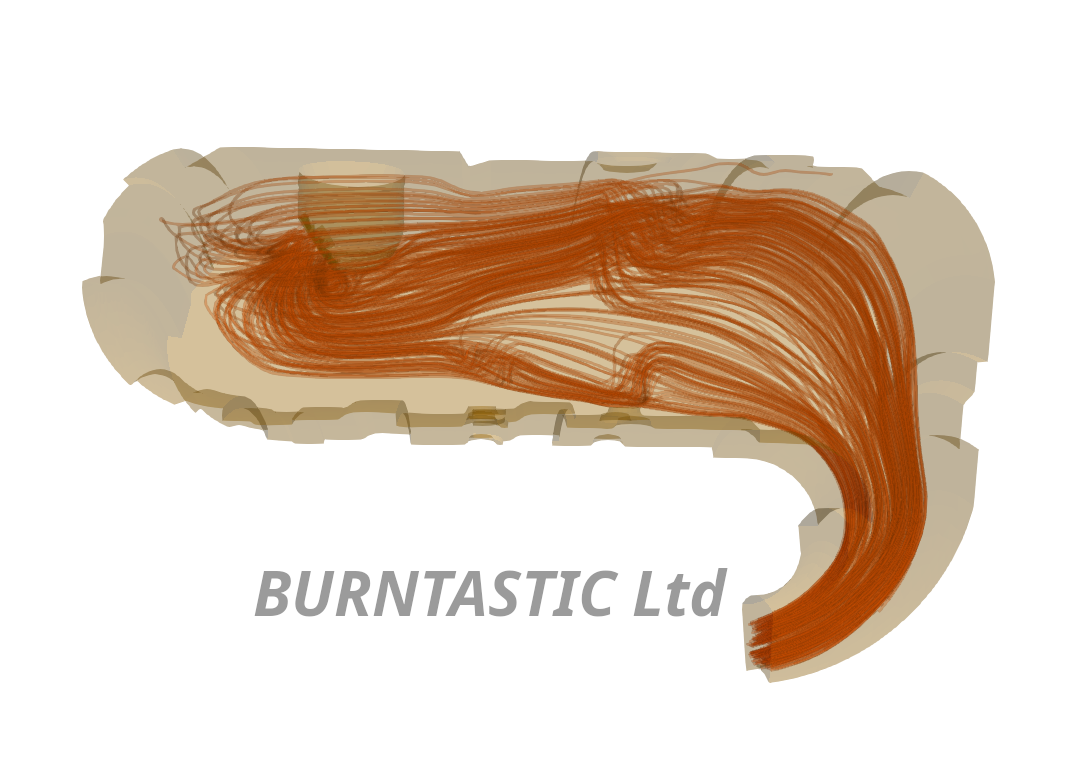
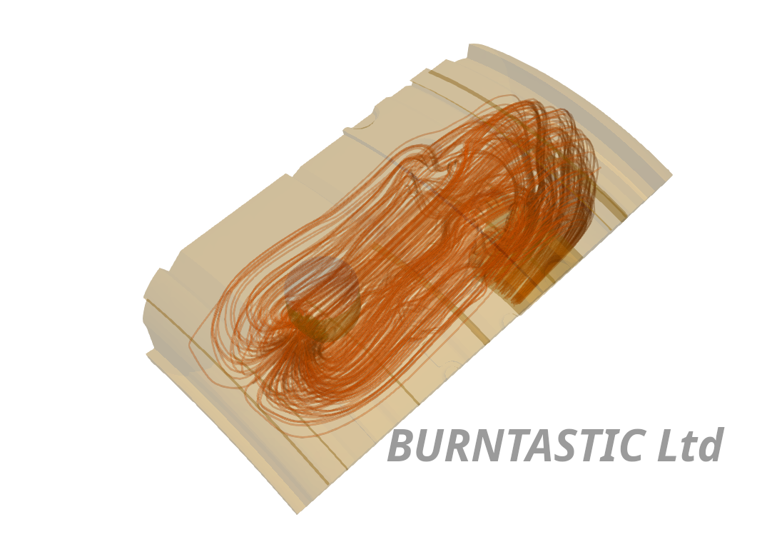
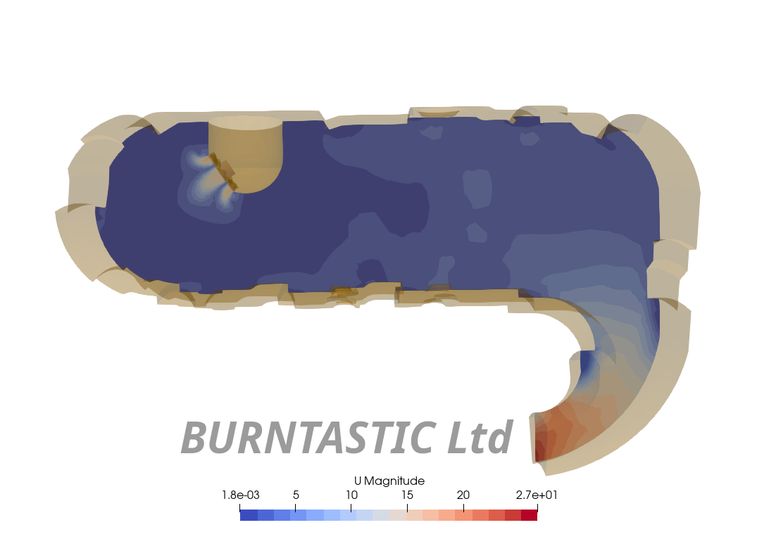
The combustion modelling results show the location of the flame alters for the different fuels. This will be shown in a latter blog post.
For anyone interested in the geometry or mesh files - please contact me using the contact page.
References
The original design information (geometry etc.) is available publicly via the links show below.
USARTL-TR-78-55A T. W Bruce H.C. Mongia, R. S. Reynolds Combustor Design Criterial Validation Volume III, AiResearch Manufacturing Company of Arizona
avaiable: https://apps.dtic.mil/sti/pdfs/ADA067657.pdf
USARTL-TR-78-55B H.C. Mongia, R. S. Reynolds, E. Coleman, T. Bruce Combustor Design Criterial Validation Volume III, AiResearch Manufacturing Company of Arizona
avaiable: https://apps.dtic.mil/sti/pdfs/ADA067689.pdf
USARTL-TR-78-55C H.C. Mongia, R. S. Reynolds Combustor Design Criterial Validation Volume III, AiResearch Manufacturing Company of Arizona
Latest Posts
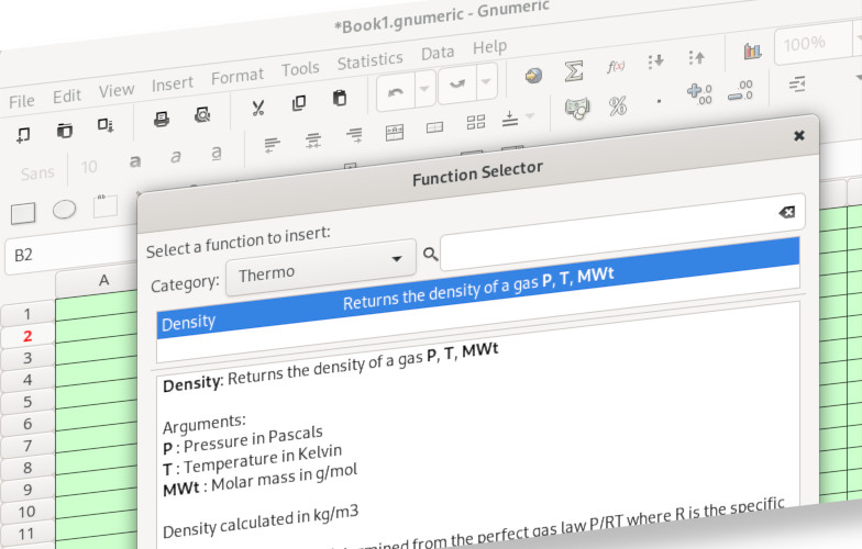
Gnumeric - function writing tutorial
11 Apr 2023
OpenFoam - Micro Combustor
09 Apr 2023